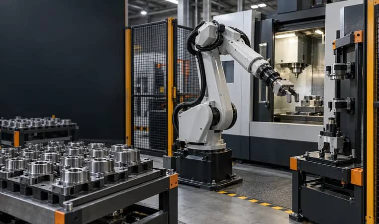
Seven questions that decide the architecture
Answer these with the planned product mix and operating sequence, not a theoretical list of future possibilities.
- Different contact jobs
- Do variants truly require different grippers, or could controlled fingers or adapters cover them?
- Changeover rhythm
- How often do tools change, and can the change occur outside the bottleneck cycle?
- Tool interface
- Payload, center of gravity, utilities, sensing, cable routing and permitted dock orientation.
- Cell footprint
- Dock, tool storage, robot approach, maintenance access and guarded-space implication.
- Operating boundary
- Tool identification, coupling confirmation, fault response, maintenance and return-to-service validation.
Select a changer only after the saved setup or added capability is compared with every added interface and recovery task. Select a dedicated gripper only after confirming the part family and change path will remain genuinely compatible.
Define the job before comparing the hardware
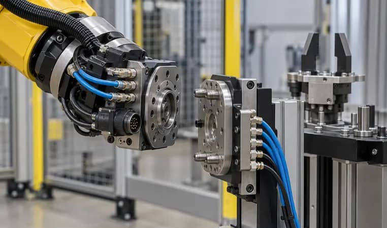
A tool changer is an interface system, not simply a flexible wrist. A3 describes the basic arrangement: a master plate stays with the robot and each end effector receives a tool plate; the robot docks to exchange tools. ATI describes master and tool sides plus the utility connections that may pass through the coupling. Those descriptions explain the category, but they do not decide whether the added stations, utilities and program states are justified in a particular cell.
Start with the part-family map. List each part’s required contact surfaces, mass, orientation, machine access, process-tool need and quality risk. If one verified gripper concept can safely handle the planned family with controlled jaw changes, a fixed tool may preserve a simpler path. If jobs need incompatible gripping, inspection, process or handling functions, a changer may make the cell route possible—but it creates its own operating system.
- Separate actual launched variants from unapproved future possibilities.
- Identify whether changeover occurs during a machine bottleneck or an available overlap period.
- List every utility that must cross the wrist, not only air or electrical power.
Further reading: Association for Advancing Automation — Tool Changers ↗ · ATI Industrial Automation — Robot Tool Changer ↗
Dedicated tool or automatic changer: compare the operating model
Best explored where one stable contact concept covers the released part family.
Best explored where incompatible tools create a real, repeatable production need.
Compare utilities, moments, cables, tool ID and docking access—not purchase price alone.
Every architecture needs a safe answer for an uncertain tool or part state.
Compare complete changeover time, not only docking time
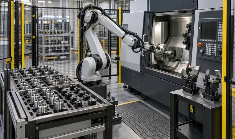
The commercial question is not how quickly a coupler can lock in isolation. It is the total time and reliability cost of leaving a work point, travelling to a stand, locating the next tool, coupling, confirming identity and utilities, returning to the work point and recovering if any step is uncertain. Compare that against a dedicated gripper’s simpler path and the cost of manual jaw changes, duplicate cells or planned downtime.
Use an assumption table, not a promised throughput number. A high mix may make an added tool exchange reasonable when it avoids a longer manual setup or enables otherwise incompatible work. A low mix may favor a dedicated tool when the tool dock adds time, reach constraints and maintenance without solving a material planning problem.
- Time the full move, dock, confirm and return sequence in the intended layout.
- Check whether tool change uses robot availability that could be producing parts.
- Include commissioning and revalidation time when a new tool or part family is introduced.
Further reading: Association for Advancing Automation — Tool Changers ↗
Treat the changer as a mechanical, utility and software boundary
A coupling has to carry more than a nominal payload. Review tool mass, center of gravity, moments, acceleration, orientation and the service state of every utility connection. ATI notes that robot tool changers can pass electrical, pneumatic, water and other utilities depending on the selected interface. The required modules, connections and validation depend on the specific tool and project.
The control model must also know which tool is present and what condition permits motion. Define dock clear, tool present, coupling confirmed, utilities ready, tool ID, safe retreat and fault/recovery states. A mechanical connection without an agreed confirmation and restart path turns a flexible concept into a difficult service event.
- Check robot payload and wrist moments with the heaviest selected tool and part.
- Protect cables and hoses through docking, robot motion and maintenance access.
- Define tool identification and the response to an incomplete or unexpected coupling state.
Further reading: ATI Industrial Automation — Robot Tool Changer ↗ · ATI Industrial Automation — Overview Catalog ↗
A buyer’s tool-architecture selection flow
Released SKU mix and contact jobs
Changeover, utilities and footprint
Complete cycle and service boundary
Docking, tool ID and part trials
Acceptance, recovery and support
Plan quality, service and recovery before capital approval
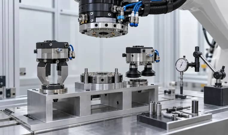
A dedicated gripper concentrates service on one contact tool; a changer adds master, tool plate, dock, interfaces and stored tools. Neither is automatically lower risk. The best choice is the one whose checks, access and failure containment fit the operating team and planned family. Include jaw wear, tool storage condition, docking alignment, utility leaks, sensor checks and any required re-teach after service.
Build the acceptance plan around real routes: select tool, pick it up, prove utility and identification, run representative parts, return it, handle a failed dock and restore the cell after maintenance. Assign the machine owner, integrator and operations team their responsibilities. This turns the investment boundary into a reviewable decision rather than a headline feature.
- Specify the storage and protection condition for every docked tool.
- Provide a controlled manual-recovery and return-to-service procedure.
- Keep future tooling as an explicit option unless it has a defined interface and validation scope.
Further reading: Association for Advancing Automation — Physical AI in the Real World ↗
Tool changer versus dedicated gripper comparison matrix
Use this matrix with the released product mix. It identifies what to prove before selecting an architecture; it does not make an investment recommendation by itself.
Copy the rows into your RFQ or investment worksheet.
| Decision area | Dedicated gripper: establish | Tool changer: establish | Evidence to request |
|---|---|---|---|
| Part-family fit | One contact concept or controlled jaw path | Incompatible tasks can be ignored | Part-family/contact map |
| Changeover | Manual or planned jaw/setup time | Change frequency is immaterial | Released schedule and observed setup |
| Cycle effect | Fixed operating path and handling time | No consequence of future mix | Sequence timing with assumptions |
| Docking route | Not applicable or protected manual station | A dock fits anywhere | Layout, approach and clearance check |
| Utilities | Single-tool air, power, sensing and cable route | Every future utility is already available | Interface schedule |
| Robot loading | Tool, adapters and part mass/moments | Tool plate mass is negligible | Robot load calculation |
| Tool identity | Fixed program/tool configuration | Tool selection cannot be wrong | Configuration-control method |
| Maintenance | Jaws, sensors and contact parts | Docked tools need no service | Access and spare-parts plan |
| Exception recovery | Part or grip recovery route | Coupling error is a routine reset | Witnessed exception scenarios |
| Acceptance | Representative parts and released route | Future tools are accepted by implication | Revision-controlled test record |
Frequently asked questions
When does a robot tool changer make sense for machine tending?
Consider it when the released part mix requires genuinely incompatible end effectors or another repeated tool function, and the cell can support the dock, utilities, motion, maintenance and recovery path. Validate the complete change sequence, not just coupling time.
Is a dedicated gripper always faster?
A dedicated gripper can remove docking motions and interface states, but the relevant comparison includes manual changeover, SKU mix, part presentation, planned downtime and the complete operating sequence. Time the intended route before deciding.
What interfaces must a tool changer review?
Review mechanical loading, tool and part moments, docking alignment, electrical/pneumatic/fluid connections where used, cable routing, tool identification, coupling confirmation, fault response and service access. The exact configuration is project-specific.
Can a changer be added later?
Possibly, but it may affect robot loading, reach, tooling interfaces, cable routing, dock footprint, guarding, program states and acceptance scope. Keep it as a defined future option rather than assuming retrofit will be simple.
Original sources and project boundary
Choose the tool architecture from the released production model
Send the released part-family list, changeover pattern, machine sequence, tool requirements, available footprint and service expectations. We can help organize the fixed-tool and change-tool inputs into a reviewable project scope.
Discuss EOAT architecture ↗