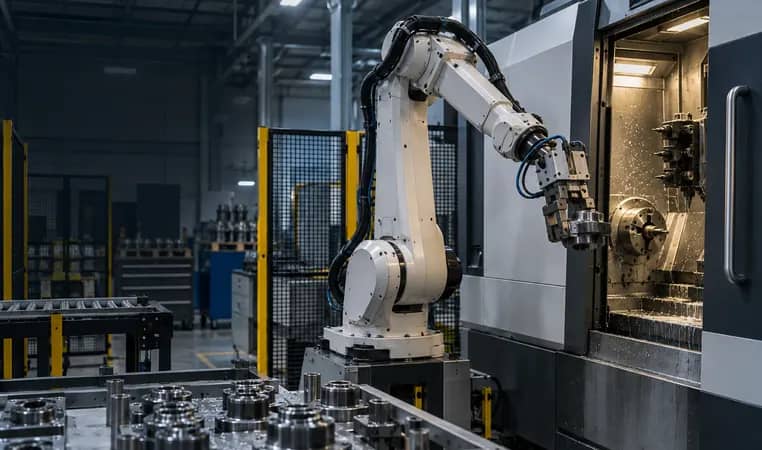
Five inputs to confirm before choosing the gripper
Capture these with representative raw and finished parts, including the conditions that occur between cleaning cycles.
- Contact surfaces
- Permitted grip and locator faces, finish sensitivity, burr risk and the directions the jaws may load.
- Variation envelope
- Part dimensions, mass, center of gravity, temperature, oil/coolant film and presentation repeatability.
- Machine interaction
- Chuck or vise position, allowable approach, handoff condition, available clearance and machine-side confirmation.
- Confirmation logic
- How the cell identifies a part, an incomplete grip, seating, release and a suspect condition.
- Service and recovery
- Finger wear, spare contact parts, inspection interval, drop containment and restart authority.
Do not release EOAT from a nominal CAD pick alone. Confirm the contact concept and recovery sequence with representative parts, actual machine access and the same coolant, chips and presentation conditions expected in production.
Start with the part and its condition at pickup
A machine tending gripper is the contact point between the robot and a part that may arrive warm, oily, wet, burred or slightly displaced. Define what the fingers may touch, which surfaces must stay cosmetic or functional, and whether the part can flex when clamped. Also record the complete motion: the part has to remain secure during acceleration, deceleration, direction changes and the machine handoff—not merely while the robot is still.
Festo’s application-first selection guidance lists geometry, center of gravity, friction, sensitivity, tolerance and environmental influences such as oil, humidity and temperature. Those are starting inputs. The final jaw geometry, actuation and validation still belong to the actual workpiece, robot motion and machine interface.
- Collect raw and finished samples, including the agreed variation limits.
- Mark allowable grip faces and protected locating faces on the part drawing.
- Check the gripper, adapters, cables and part against robot payload and moment limits together.
Further reading: Festo — Robot Gripper Selection in 5 Steps ↗
Gripper selection matrix: turn conditions into proof
Oil, chips, burrs, finish and deformation define viable contact options.
Tray, machine locator, chuck and clearance decide the jaw envelope.
Define what evidence permits motion, placement and restart.
Provide containment, access and ownership for doubtful or dropped parts.
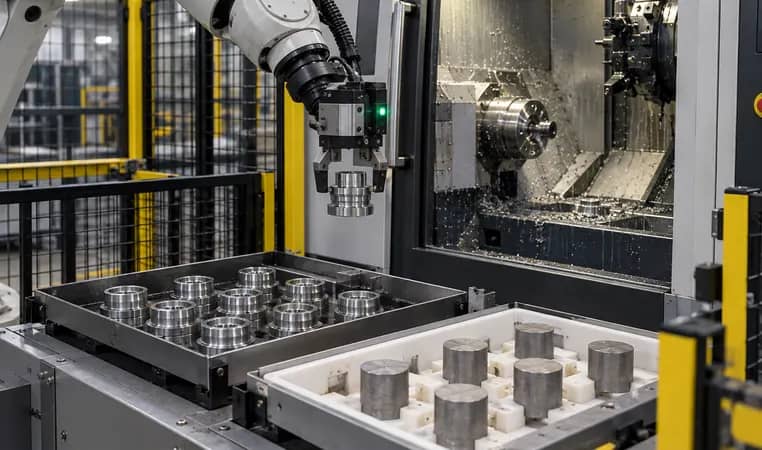
Make locating and gripping work as one handoff
The gripper cannot correct a vague part presentation by itself. Identify how a blank is oriented in the tray, how it is approached without clipping adjacent parts, how the machine fixture accepts it and what proves it has seated. Vention’s machine-tending design guidance notes that finger size and opening envelope can limit part density and collision clearance in a tray. Treat that staging geometry as an EOAT requirement.
Separate the tasks: locators establish part position, jaws retain the part, sensors or machine feedback confirm a defined condition, and software decides whether a cycle may continue. If a part can arrive rotated, doubled, absent or outside the permitted position, assign a detection and containment method before the robot program is released.
- Draw the finger-open envelope at every tray and machine approach point.
- Specify the path to a good-part destination, suspect nest and rejected-part containment.
- Record who confirms workholding state and who owns the handoff acceptance test.
Further reading: Vention — Designing Machine Tending Equipment ↗
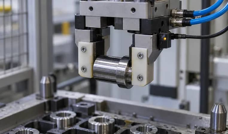
Design grip confirmation and exception handling together
Grip confirmation should answer a usable question: may the robot proceed with this part under this condition? It can combine sensor feedback, motion response, machine feedback or another selected method, but the selected method must be checked with the real part and failure modes. A generic EOAT definition does not make any particular sensing arrangement sufficient.
Create named responses for empty pickup, incomplete closure, unexpected part state, lost part and failed release. For each response, state whether the robot holds, retreats, places the part in a recovery location or waits for an authorized person. This makes recovery an engineered interface rather than a late programming exception.
- Test nominal, no-part, wrong-position and uncertain-grip conditions before acceptance.
- Keep a safe, accessible recovery location outside the machine envelope.
- Record reset authority and the evidence required before a cycle resumes.
Further reading: Association for Advancing Automation — What Is EOAT? ↗
From sample part to validated gripper concept
Part, surfaces, variation and environment
Tray, machine locator and approach path
Jaws, contact pads and confirmation
Nominal and exception part states
Service, recovery and acceptance record
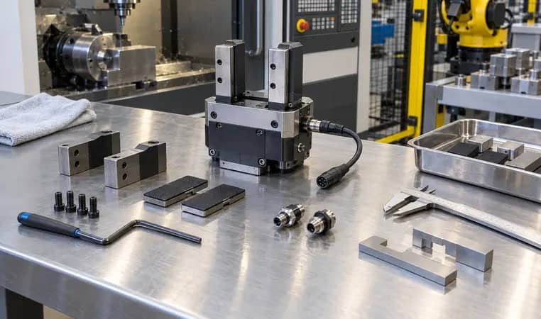
Plan EOAT service around the process, not only the component
Fingers, pads, fasteners, seals, fittings and sensing cables experience the same coolant, chips and contact events as the production cell. Give maintenance staff access to inspect contact faces and replace wear elements without defeating the guarded cell or disturbing calibrated locations. Keep a spare strategy for the elements that can stop production, but base intervals on observed wear and supplier guidance rather than an invented schedule.
The buyer’s deliverable is a concise support package: drawing revision, allowable contact surfaces, service access, inspection points, approved spares and a recovery instruction. That package makes an EOAT quotation comparable and prevents an apparently simple gripper from carrying hidden integration work.
- Show tool access with the robot parked and the machine in the agreed service state.
- Document torque, alignment and sensing checks that affect a returned-to-service tool.
- Link every change of jaws or part family to controlled validation before production use.
Further reading: Association for Advancing Automation — Physical AI in the Real World ↗
Machine tending gripper selection checklist
Use the rows to compare proposed EOAT concepts. The evidence column should contain a project-specific observation, drawing, test or owner—not a generic assurance.
Copy the rows into your RFQ or investment worksheet.
| Selection condition | Define before selection | Do not assume | Evidence to request |
|---|---|---|---|
| Grip surface | Permitted faces, friction condition and marking limits | A clean, uniform surface on every part | Marked part drawing and representative samples |
| Part variation | Size, mass, CG and presentation range | Nominal CAD is the full envelope | Tolerance stack and sample set |
| Oil and chips | Condition at pickup, seating and release | Dry laboratory contact | Trial under agreed production condition |
| Deformation | Permitted clamp load path and protected zones | Rigid behavior from material name alone | Part/fixture review and trial |
| Machine locator | Datum, seat and chuck/vise handoff | The gripper establishes final location | Machine approach and seating check |
| Grip confirmation | Normal, no-part and uncertain-grip response | Closed jaws prove a correct part | State table and exception test |
| Tray clearance | Finger-open envelope and adjacent-part clearance | Part spacing alone is sufficient | Layout overlay or physical trial |
| Dropped part | Containment, detection and recovery authority | Operator intervention needs no plan | Witnessed recovery scenario |
| EOAT service | Wear access, sensing check and spare elements | Tool maintenance is outside cell scope | Service-access review and support list |
| Acceptance | Part states, motion and handoff tests | One successful pickup proves readiness | Revision-controlled acceptance record |
Frequently asked questions
How do I choose a gripper for oily machined parts?
Begin with the real pickup surface, coolant or oil film, chip condition, part orientation and motion path. Then validate the selected contact concept with representative parts. Do not use a dry demonstration or nominal CAD alone as proof of production grip reliability.
Does a closed gripper prove the part is correctly held?
Not necessarily. A closed position can occur with no part, a wrong part position or an incomplete grip. Define what confirmation is required for your part, then test normal and exception states with the selected sensing and control logic.
Can one gripper handle every part family?
Sometimes, but only where geometry, contact surfaces, mass, variation, machine access and required placement are compatible. Compare interchangeable jaws, multiple dedicated tools and an automatic changer against the real changeover and validation work.
What should be included in a gripper acceptance test?
Use representative raw and finished parts to witness pickup, motion, placement, machine handoff, no-part response, uncertain-grip response, recovery and returned-to-service checks after the agreed maintenance action.
Original sources and project boundary
Turn the part interface into a reviewable EOAT scope
Share part drawings, samples or condition photos, machine workholding details, presentation method, target cycle and exception concerns. We can help organize the gripper, staging and control questions that need to be closed for a project-specific proposal.
Discuss machine tending EOAT ↗