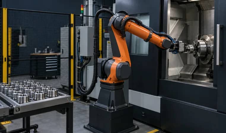
Five inputs to freeze before detailed integration
Request these five inputs in the same revision as the part drawing and cell concept.
- Machine access
- Door stroke, opening sequence, spindle/chuck envelope, service clearances and any manual intervention.
- Part control
- Raw and finished part presentation, gripper contact surfaces, orientation, chuck confirmation and drop/reject route.
- Operating states
- Named signals and permitted transitions for ready, machining, complete, robot-in, fault, hold and restart.
- Process environment
- Chip, coolant, air-blow, wash-down and sensing conditions that can affect gripping, seating or visibility.
- Recovery and proof
- What happens after a dropped part, open door, failed clamp, alarm or interrupted cycle, and how acceptance will be witnessed.
Release a detailed interface design only when the machine supplier, integrator and plant owner agree on the same part revision, state table, recovery authority and acceptance record. A signal list alone does not establish a safe or production-ready cell.
Map the physical boundary before selecting signals
Begin at the machine door, not the robot catalog. Measure the door path, opening time, chuck or vise geometry, spindle orientation requirement, fixture loading face and the positions a gripper must approach and leave. Include the actual part family, raw stock condition, burrs, coolant carryover and a rejected-part route. A robot that reaches a nominal workpiece may still lack a collision-free approach or a reliable way to confirm seating.
Robotiq's machine-tending training describes the practical dependency between automated door operation, workholding, robot handling and the machine/robot handshake. RBTX similarly calls out accessible I/O, an automated door and consistent parts as preparation topics. Those are useful prompts, not a promise that a particular CNC can be integrated without a machine-specific review.
- Freeze the maximum and minimum part, gripper fingers and chuck jaw travel.
- State who owns workholding automation, part-present confirmation and rejected-part containment.
- Record every operator task that remains: replenishment, gauging, chip clearing, tool change and intervention.
Further reading: Robotiq — Machine Tending Robotic Cell Design ↗ · igus RBTX Learn — Get CNC Machine Automation Ready ↗
Four documents that prevent an interface gap
Door, chuck, part, EOAT, tray and service envelope in one controlled revision.
Meaning, source, destination, timeout and restart authority for each operating transition.
Raw/finished part orientation, chips, coolant, acceptable surfaces and reject route.
Nominal and exception tests, evidence, owner and closure path.
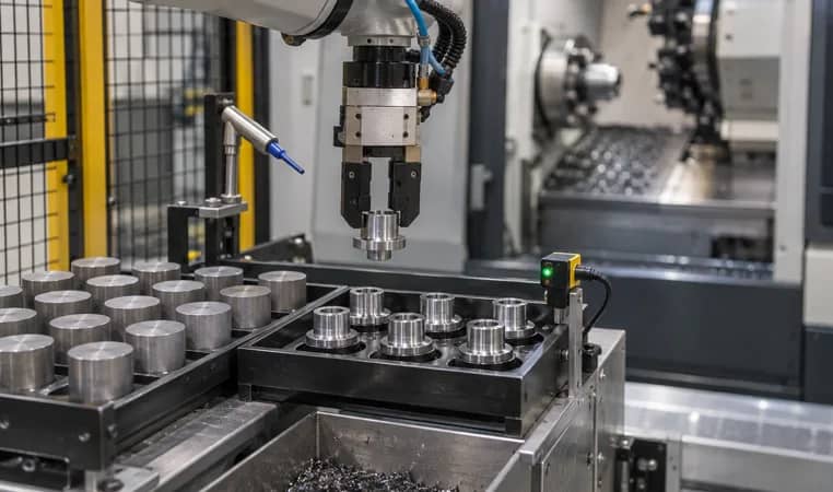
Write a state table, not a vague I/O request
The integration boundary is a controlled conversation. Define which party produces and consumes each state, its meaning, the permitted next state, timeout, alarm response and reset authority. At minimum, the project needs an unambiguous definition for machine available, cycle complete, robot permitted to enter, robot clear, part clamped or unclamped, and fault/hold. The exact signal names, electrical interface and safety architecture are machine- and project-specific.
FANUC documents Robot ON-SITE and Robot CONNECT as product-specific paths for connecting certain FANUC CNC and robot systems. Its published material also distinguishes a connection function from a safety interface in some configurations. Use manufacturer documentation to define the actual supported scope; do not assume that Ethernet connectivity or a cycle-complete bit covers every control or safety responsibility.
- Name the source, destination, normal state and timeout for every signal.
- Separate production handshake, quality/part confirmation and safety functions in the design package.
- Test loss of signal, power restoration and manual mode with named restart authority.
Further reading: FANUC — Robot and CNC Integration ↗
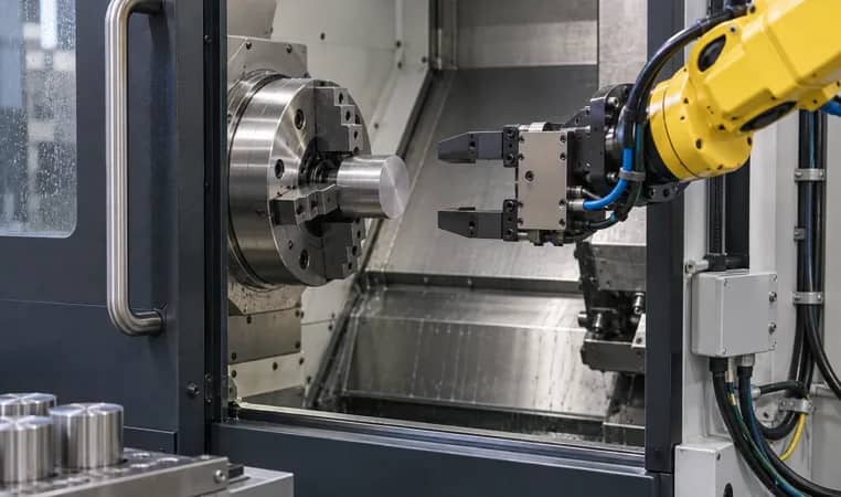
Treat chips, coolant and staging as integration inputs
Chip nests, coolant film, swarf on locators and inconsistent raw-part presentation can turn an otherwise correct sequence into an intermittent cell. The gripper must tolerate the part surface and mass condition actually arriving at the machine. Staging must make the correct blank accessible, protect finished parts and make a no-part or wrong-part condition visible to the logic.
Make cleaning and recovery explicit. Decide whether the machine, robot, an air-blow device or an operator removes chips; decide where coolant drains; and decide which condition blocks a new cycle. Robotiq's guidance highlights chip/coolant management and automated workholding as repeatability issues. It does not replace validation with the selected material, tooling and coolant.
- Describe allowable chip/coolant condition at pickup, clamp and unload.
- Use a physical location and a logic state for good, suspect and rejected parts.
- Review EOAT service, finger wear and gripper confirmation alongside the cycle model.
Further reading: Robotiq — Machine Tending Robotic Cell Design ↗
A practical integration release flow
Part, door, workholding and access
States, owners and material flow
EOAT, chips, coolant and part seating
Nominal cycle and recovery tests
As-built records and escalation
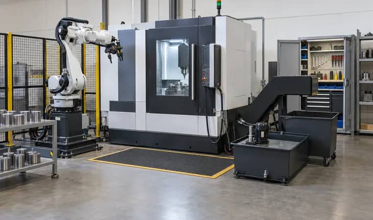
Turn exceptions into an acceptance plan
A demonstration of one nominal cycle is not an integration acceptance plan. Build tests around the real failure paths: empty tray, double blank, wrong orientation, door not open, clamp not confirmed, robot unable to pick, machine alarm, cycle interruption and controlled restart. The purpose is not to prescribe a universal recovery sequence; it is to assign who detects, contains, clears and authorizes each one.
At factory and site acceptance, witness the agreed operating states, part handling, changeover, quality confirmation and recovery scenarios against a revision-controlled checklist. Keep the machine manual, robot program, I/O table and operator instructions aligned. If a feature is outside the selected machine or robot supplier's documented scope, keep it open until the responsible party provides a verified design response.
- Use representative raw and finished parts, including agreed edge cases.
- Record acceptance criteria, owner, result and unresolved action for every scenario.
- Handover the as-built state table, backed-up programs and escalation contacts with the cell.
Further reading: FANUC — Robot and CNC Integration ↗
CNC machine tending interface responsibility checklist
Use this as a design and FAT/SAT worksheet. It identifies a decision to close; it does not supply a generic machine wiring or safety design.
Copy the rows into your RFQ or investment worksheet.
| Interface | Plant / machine owner confirms | Integrator / supplier defines | Acceptance evidence |
|---|---|---|---|
| Machine door | Travel, cycle, manual access and service constraints | Actuation method, sequence and interlocks in the chosen scope | Observed open/close sequence with agreed modes |
| Chuck or vise | Part datum, clamping limits and confirmation available | Grip/seat logic and interface boundary | Representative part clamp/unclamp trial |
| Robot and EOAT | Part family, surface limits, mass and variants | Reach, fingers, routing, sensing and service plan | Pick/place and collision review with real parts |
| CNC / robot I/O | Supported machine interface and documentation | Named state table, timeout, diagnostics and ownership | I/O checkout and simulated state transitions |
| Cycle release | Machine cycle prerequisites and quality hold points | Sequence that grants start and reports completion | Witnessed nominal-cycle record |
| Part staging | Raw/finished quantities, replenishment and packaging | Presentation, orientation, no-part and reject logic | Tray/rack run including empty and wrong-part cases |
| Chips and coolant | Coolant type, chip behavior and disposal limits | Cleaning action, drainage and blocked-cycle conditions | Repeated loading/unloading observation |
| Safety boundary | Site rules, risk inputs and required approvals | Project-specific protective design and validation plan | Approved task-based validation record |
| Recovery | Escalation owner and permitted manual tasks | Alarm messages, containment and restart sequence | Witnessed fault and controlled-restart tests |
| Handover | Operators, maintainers and local support route | Training, backups, as-built records and warranty boundary | Signed document and training handover |
Frequently asked questions
Which CNC signals are required for machine tending?
There is no universal fixed list. Define machine-specific states for availability, permitted entry, clamp/part condition, cycle completion, faults and restart authority with the CNC supplier, robot integrator and plant owner.
Can a robot open every CNC door and operate every chuck?
No. Door, workholding, controls and safety interfaces depend on the selected machine and scope. Verify the supported interface, mechanics, access and protective design for the exact machine before committing.
Why are chips and coolant part of integration?
They can affect gripping, part seating, sensing, staging and recovery. Describe the real material condition and decide how cleaning, drainage and no-go conditions are handled and tested.
What should site acceptance include?
In addition to nominal cycles, test agreed part variants, material presentation, exception detection, fault containment, restart authority, records and operator handover with the actual equipment and parts.
Original sources and scope boundary
Build a machine-tending interface pack
Send the CNC model, part drawings, workholding/door information, current handling flow, expected variants and site constraints. We can define the open interfaces and a project-specific validation path.
Discuss machine tending ↗