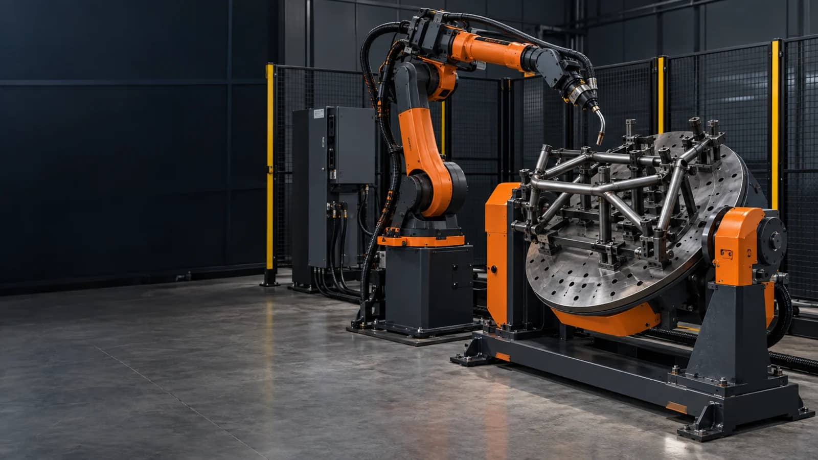
Five inputs that make a positioner interface reviewable
Capture these from the released part, fixture and cell concept. Each item needs an owner and a validation action.
- Workpiece package
- Mass, centre of gravity, inertia, envelope and fixture.
- Mechanical axis
- Faceplate, mounting, range, speed and physical stops.
- Motion model
- Indexing, time synchronization or full frame tracking.
- Control and safety
- Drive, feedback, limits, safe state and ownership.
- Release evidence
- Calibration, path trial, exception response and FAT record.
Do not approve a positioner because its rated load looks sufficient. The fixture, centre of gravity, inertia, axis configuration, controller setup, calibration, safe response and representative motion all have to work together in the released cell.
Start with the moving workpiece, not the positioner label
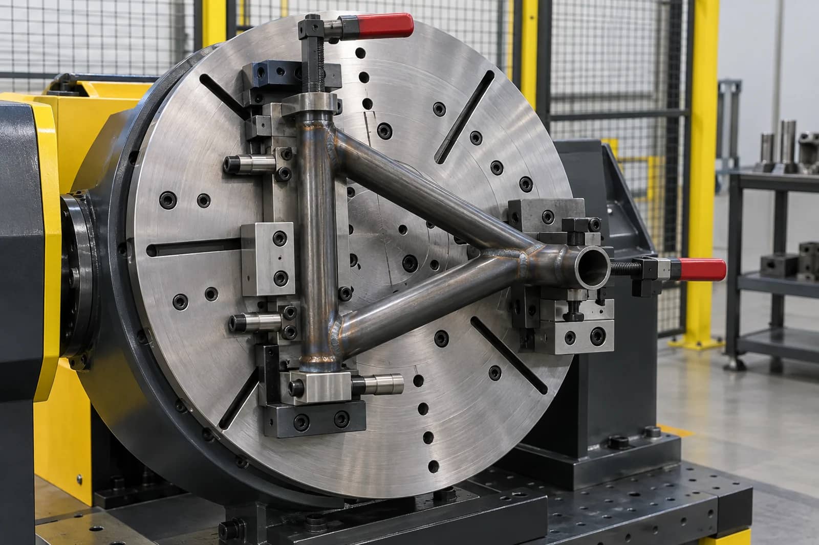
A positioner carries the fixture and every moving component attached to it. The needed input pack therefore includes the real workpiece mass, centre of gravity at each intended orientation, inertia, clamp arrangement, faceplate drawing, load/unload method and required weld access. A rating without its load condition is not enough to choose a configuration.
Cyclotron’s published interface package is useful as a procurement reminder: load data, inertia, gear ratio, servo and feedback details, mounting drawings, limits and connector information should be available before the robot integrator configures the external axis. This article turns those documents into a cross-supplier ownership list rather than claiming one universal package.
- Freeze the part and fixture revision used for the calculation.
- Record every condition that changes centre of gravity or inertia.
Further reading: Cyclotron — robotic welding positioner interface documentation ↗ · EVST — welding-positioner integration inputs ↗
Three positioner motion choices
The positioner stops before the robot runs the weld path.
Robot and axis arrive at defined targets together.
The robot follows a path relative to the moving part frame.
Verify the selected behavior with the actual configuration.
Choose the motion relationship before programming the weld
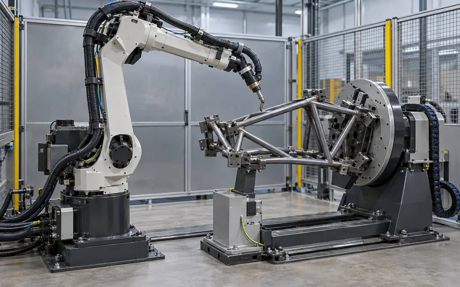
There are different jobs hidden behind the phrase ‘robot and positioner integration’. A positioner can index between welds, arrive at a target at the same time as the robot, or move while the robot tracks the workpiece frame. Universal Robots distinguishes time synchronization from frame tracking; using both is what it calls coordinated motion. That distinction should be explicit in the project scope.
FANUC’s coordinated-pair teaching example shows why this cannot be left to a handoff: the pair, leader axis, robot and positioner mastering, TCP and a reachable reference point are established before calibration. Use the chosen controller’s current documentation for the actual procedure and retain the calibration result with the cell record.
Further reading: Universal Robots — MotionPlus external-axis documentation ↗ · FANUC America — coordinated pair with a 1-axis positioner ↗
Make the controller, electrical and safety boundaries visible
The positioner supplier, robot integrator, welding-package supplier and site team may each own different hardware. Assign who supplies the motor and drive details, configures the external axis, connects encoder feedback, verifies grounding, owns guard and interlock interfaces, sets safe states, and troubleshoots a stop. No supplier should infer its responsibility from another supplier’s brochure.
An external axis also changes the moving envelope. Define normal movement, manual recovery, a loss-of-feedback response, power restoration, inspection after collision and the rules for returning to automatic operation. Safety design and validation are project-specific; this checklist identifies interfaces to confirm and does not certify a cell.
Further reading: Universal Robots — MotionPlus external-axis documentation ↗
From part data to a released positioner interface
Part, fixture and load condition
Axis mechanics and controller inputs
TCP, reference and zero state
Motion path and exception response
Record proof and change triggers
Release the interface with calibration and witnessable evidence
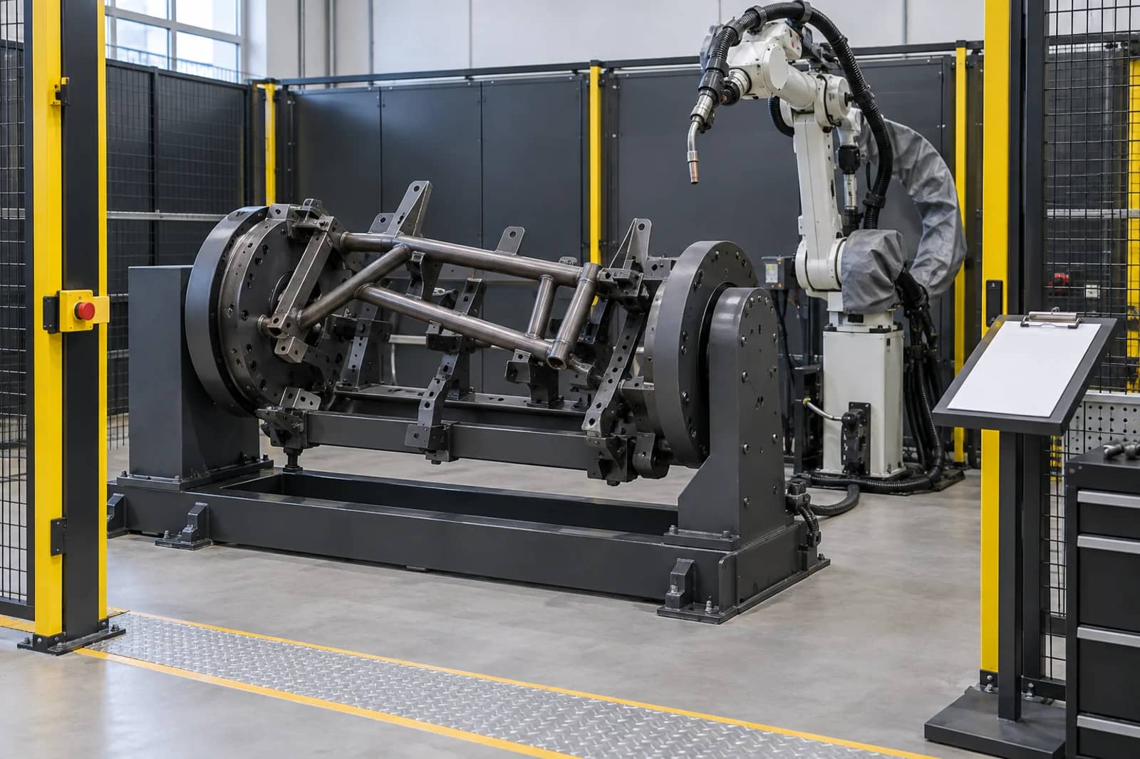
A release record should identify the part and fixture revision, the axis configuration and controller software recorded for the trial, TCP/reference method, range and speed used, test path, expected behavior, observed result, open item and owner. Witness one representative path and the defined stop or recovery behavior; a single jog at no load is not a production acceptance.
Reopen the record when the part family, fixture, faceplate, drive, controller configuration, robot tool, cable route, guard logic or sequence changes. This makes future change decisions faster because the original assumptions and proof are visible rather than embedded only in a program backup.
Further reading: FANUC America — coordinated pair with a 1-axis positioner ↗
Robot welding positioner interface checklist
Use this as a project matrix. A row is complete only when its actual configuration, owner and evidence are known.
Copy the rows into your RFQ or investment worksheet.
| Interface item | Define | Do not assume | Evidence / owner |
|---|---|---|---|
| Part and fixture | Mass, CG, inertia, envelope and clamps | Rated payload describes the loaded fixture | Released drawing and calculation owner |
| Faceplate and mounting | Pattern, adapter, fasteners and locating | Any fixture plate fits the selected axis | Interface drawing and installer |
| Axis performance | Range, speed, acceleration and stop condition | Travel and speed suit every orientation | Configuration record and motion owner |
| Drive and feedback | Servo, drive, ratio, encoder and connectors | Robot cabinet already supports the axis | Data sheet and controls owner |
| Motion relationship | Indexing, synchronized targets or frame tracking | ‘Coordinated’ means the same thing to all parties | Program concept and integrator |
| Calibration | Axis zero, mastering, TCP and reference point | A nominal CAD origin is calibrated | Calibration record and programmer |
| Cables and grounding | Routing, bend path, weld-current and service access | Static slack proves moving clearance | Route check and electrical owner |
| Safety boundary | Guarding, limits, safe stop and restart authority | Robot safety covers all external-axis states | Safety design and validation owner |
| Exception recovery | Loss of feedback, collision, power return and inspection | A reset is always an acceptable recovery | Recovery sequence and owner |
| FAT evidence | Representative path, result, open items and change triggers | One no-load jog proves production | Signed test record and disposition |
Frequently asked questions
What is a robot welding positioner interface?
It is the documented mechanical, motion, control and safety boundary between a robot, positioner, fixture and cell. It identifies the actual configuration, responsibility and evidence needed before release.
Is rated payload enough to select a welding positioner?
No. The part, fixture, centre of gravity, inertia, orientation, speed, range, mounting and duty need project-specific review. Ask for the load condition behind any rating.
When is coordinated motion needed?
Use it only when the robot must maintain its path relative to a moving workpiece during the weld. Indexing between welds or time-synchronized target moves are different control requirements.
What should positioner FAT prove?
It should prove the agreed calibration, representative path, configured range and speed, expected response to defined exceptions, open-item disposition and the responsible release record.
Original sources and project boundary
Define the positioner interface before the cell is quoted
Send the part and fixture drawings, mass and orientation data, weld map, robot preference, desired motion relationship, layout and acceptance target. We can organize the open interfaces into a project-specific review.
Discuss a positioner interface ↗