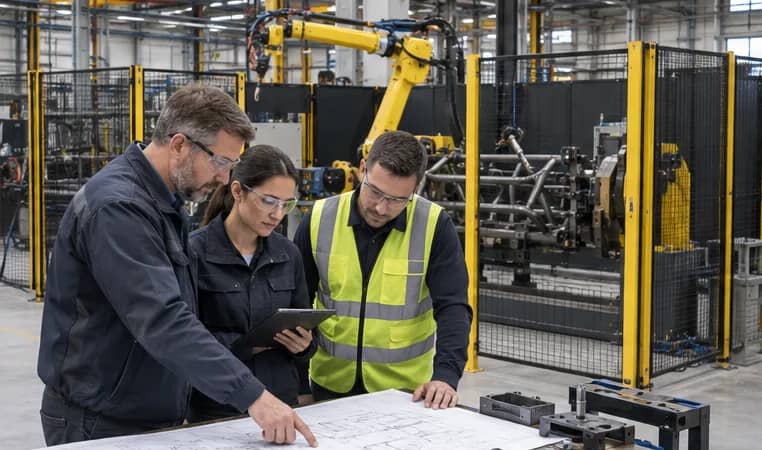
Layout design-release packet
Before fixing anchors or buying a cell, request one coordinated drawing package with these five linked views and named owners.
- Geometry
- Part families, max/min workpiece, fixture mass, clamp access, swing and removal envelope.
- Motion
- Robot base, all weld/tool poses, dress package, positioner sweep, collision and recovery paths.
- People
- Load/unload, guarding, doors, visibility, maintenance, cleaning and emergency access tasks.
- Flow
- Incoming material, staging, rejected-part route, finished goods and vehicle/pedestrian paths.
- Services
- Power, ground, gas, air, network, extraction, drain/filtration and expansion connections.
Release the floor plan only after the physical walk-through, robot/fixture motion study, task-based safety review and signed interface matrix agree on the same drawing revision. This checklist does not certify the installation.
Start with the moving part, fixture and torch
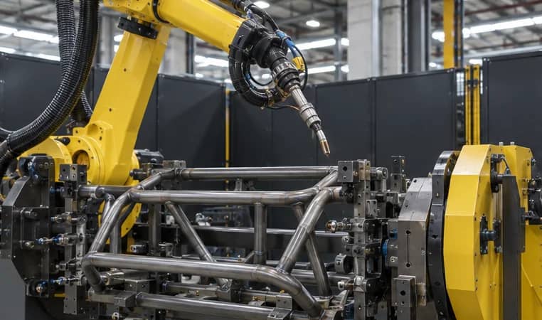
Draw more than the nominal steel part. Show clamps open and closed, locating fingers, cables, weld spatter shields, robot dress pack, gripper or torch and the full positioner rotation. Check the maximum and minimum part families, loading orientation and safe removal of a distorted or rejected assembly. A robot nominal reach circle is not proof of usable torch angle or collision-free approach.
ABB's RobotStudio materials show how offline programming can inspect reach and path configuration. Use simulation and a physical review together: represent the real fixture, tool center point, cable bend and robot/positioner coordinated motion, then trial the limiting welds. Lincoln's Flex-Fab sheet publishes product-specific swing, footprint and hood details; those numbers are not generic design clearances.
- Freeze drawing revisions and maximum workpiece plus fixture envelope.
- Check approach, weld, depart, nozzle service and abnormal recovery poses.
- Include lifting equipment or carts needed to remove a stuck or heavy part.
Further reading: ABB — RobotStudio tutorials and arc welding simulation ↗ · Lincoln Electric — Flex-Fab XHS product sheet ↗
Three drawings that must agree
Worst-case assembly, open clamps, positioner sweep and removal.
Robot/tool paths, cable routing, collision and recovery.
Guarding, handling, service, extraction, utilities and expansion.
Separate production, transfer and protected service zones
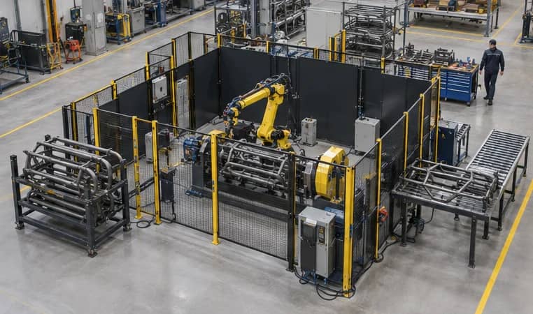
Mark four connected zones on the same plan: incoming staging, guarded process, outgoing inspection and service/utilities. Trace a part from arrival to accepted or rejected exit, including the path of pallets, carts or cranes. Then trace a person changing wire, servicing the torch, cleaning fume equipment or restoring a fixture. If these routes cross active robot motion, the layout needs redesign or a controlled task mode.
Safeguarding is determined by a task-based risk assessment, not a universal aisle or fence number. Yaskawa's safety setup and OSHA's industrial-robot guidance emphasize integrating access and maintenance into the safety concept. Define guard openings, interlocks, visibility, restart authority and isolation points with the responsible integrator and destination-site safety team.
- Infeed and outfeed must not block the guarded access needed for maintenance.
- Plan rejected-part removal and fault recovery, not just ideal production flow.
- Keep emergency and service routes clear in the installed plant, not only in CAD.
Further reading: Yaskawa SRCI — safety setup (2024-08-23) ↗ · OSHA — Industrial robot technical manual ↗
Resolve fume, power, gas and data before freezing the footprint
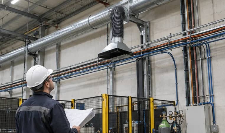
Welding fume control can need a hood or local capture, duct route, fan/filtration equipment, make-up air, inspection and service access. Lincoln Electric's product sheet distinguishes a hood from an optional extraction system with central unit and ducting—an example of why a drawn hood is not the full site interface. Define capture and compliance requirements for the actual process and jurisdiction with competent specialists.
Show electrical load and disconnect, protective earth/return path, shielding-gas and compressed-air supply, network/I-O, consumable storage and cable/hoseline routing. Check structural anchors, slab/loading, floor level and delivery/rigging route. A compact robot cell can still need substantial adjacent service and material area. Reserve realistic expansion space for a second part family or station, not an undefined blank square.
- List required utility capacity, connection point and owner on the drawing.
- Coordinate extraction ducting with crane, sprinkler, lighting and access routes.
- Keep serviceable components reachable without defeating protective measures.
Further reading: Lincoln Electric — Flex-Fab XHS product sheet ↗
Layout release sequence
Parts, floor and utilities
Material and people routes
Reach and interference
Risk and interface owners
Signed revision and site gate
Use a signed interface list as the design gate
A dimensioned plan alone does not show who supplies the extraction fan, moves a gas line or validates an interlock. The table below turns layout into a handoff: each row needs project-specific coordinates/limits, customer or integrator ownership, drawing reference and closure evidence. Resolve excluded work before issuing purchase orders or civil works.
Ask for a coordinated layout revision, robot reach/collision review, representative part trial, task-based risk assessment and installation readiness check. The fixture guide handles locating details; the FAT guide handles pre-shipment acceptance; this page concentrates on the floor-plan decision. Send the site drawing, workpieces, throughput target, utilities and destination to develop a scoped welding-cell concept.
- Do not release anchors from a brochure footprint alone.
- Escalate any ownership gap before shipment and retain the final as-built revision.
- Reassess after a part, fixture, process or building change.
Further reading: ABB — RobotStudio tutorials and arc welding simulation ↗
Four-zone floor-plan logic (not a scaled safety drawing)
Raw parts, kitting, lift/cart approach and operator loading.
Robot, positioner, full fixture sweep and controlled access.
Cooling, accepted-part check, rejection and onward flow.
Torch, fume equipment, power/gas/air/data and maintenance path.
Layout interface ownership and release matrix
Enter a named owner, drawing revision and acceptance evidence for every row; ‘by others’ is not an owner. No dimension below substitutes for the project risk assessment.
Copy the rows into your RFQ or investment worksheet.
| Interface | Buyer/site to provide | Cell supplier/integrator to define | Release evidence |
|---|---|---|---|
| Part and fixture envelope | Drawing revisions, mass, variants and lift method | Fixture/clamp sweep and removal concept | Joint envelope drawing and trial part IDs |
| Robot and torch reach | Weld list and quality/access criteria | Base pose, path, cable and collision study | Reach simulation plus limiting-part trial |
| Positioner motion | Part inertia, loading orientation, floor constraints | Axes, swing, payload and guarding boundary | Motion study and approved arrangement |
| Safeguarded access | Tasks, personnel routes and site safety rules | Risk-assessment-led guard/control design | Approved risk review and validation plan |
| Infeed / outfeed | Pallet/cart/crane route and inspection location | Load interface and reject-part recovery | Walk-through with actual handling method |
| Maintenance access | Facility aisle and isolation policy | Service-door, torch, source and fixture access | Maintenance task simulation and sign-off |
| Fume extraction | Air system capacity, permit and discharge route | Capture point, hood/duct interface and pressure needs | Ventilation design and specialist approval |
| Power, gas, air and data | Available capacity, connection points, grounding | Cell loads, connectors, I/O and cable paths | Coordinated utility schedule and I/O test |
| Floor, rigging and anchors | Slab data, delivery route and building constraints | Weights, anchor pattern and installation loads | Site readiness and engineer-approved plan |
| Future expansion | Forecast variants and reserved floor area | Modular interfaces and upgrade assumptions | Revision-controlled expansion sketch |
Frequently asked questions
Can I size the floor area from a robot reach radius?
No. Add fixture and positioner sweep, guarding, material flow, service access, extraction, utilities and the actual handling route. Verify reach and interference in the project layout.
What is the universal safety distance around a welding robot?
There is no one layout distance appropriate to every cell. The responsible team must use applicable standards, destination requirements and a task-based risk assessment to design and validate safeguards.
Does an offline simulation approve the installation?
No. It can reveal reach and collision issues but does not replace physical trials, site review, risk assessment, safety validation or commissioning.
Who provides the fume extraction system?
That is a contract and interface decision. Record capture equipment, fan/filter, ducting, discharge, utility capacity, permits, installation and proof of performance with named owners.
Original references
Turn your floor plan into a cell concept
Send a dimensioned site drawing, part and fixture data, weld access needs, handling route, utilities and destination. Request a coordinated layout, responsibility schedule and validation plan.
Request a layout review ↗