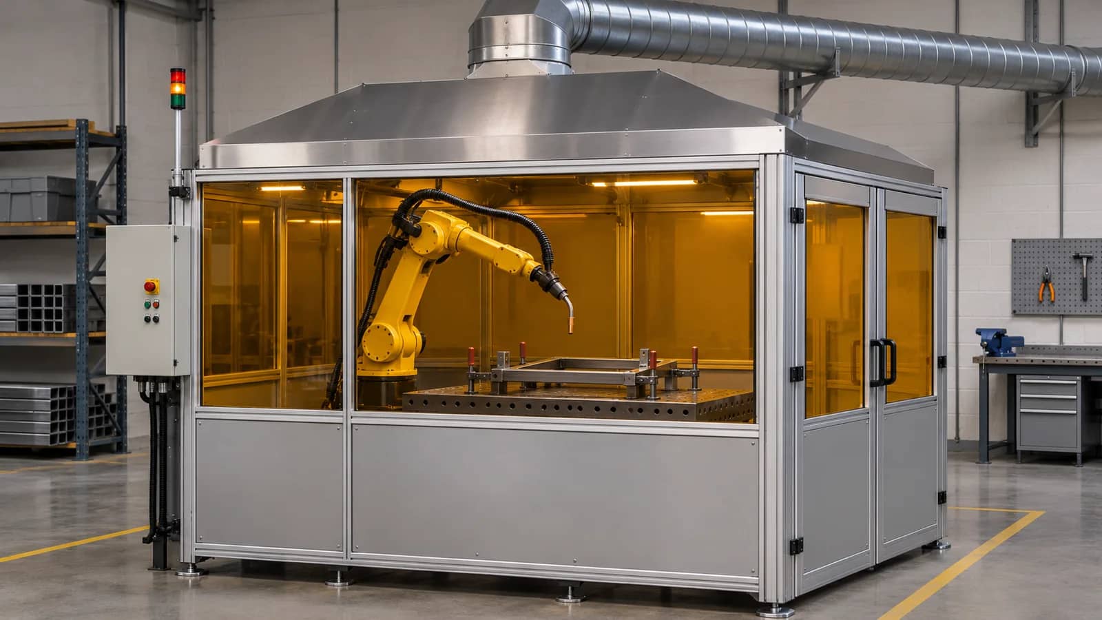
Describe the source and the operating states
Start the RFQ with the welding process, base material, coatings, filler, weld locations and production schedule. Identify other operations such as cleaning or grinding separately. Ask the ventilation designer to confirm the contaminant and hazard assumptions before choosing the equipment. Include the expected combination of active stations because shared branches can change the available flow at each pickup.
Record where people are during production, loading, inspection and service. Give the designer drawings with the loading openings, proposed capture positions and likely drafts. Define which conditions belong in the test plan, including the least favorable approved seam orientation or open access condition if it occurs during welding.
Further reading: Donaldson, weld fume source and collection layout ↗
Compare capture choices before freezing layout
Moves with the source. Check wrist, hose and shielding.
Captures from a defined zone. Check openings and seam positions.
Collects from several pickups. Verify branch balance at concurrent loads.
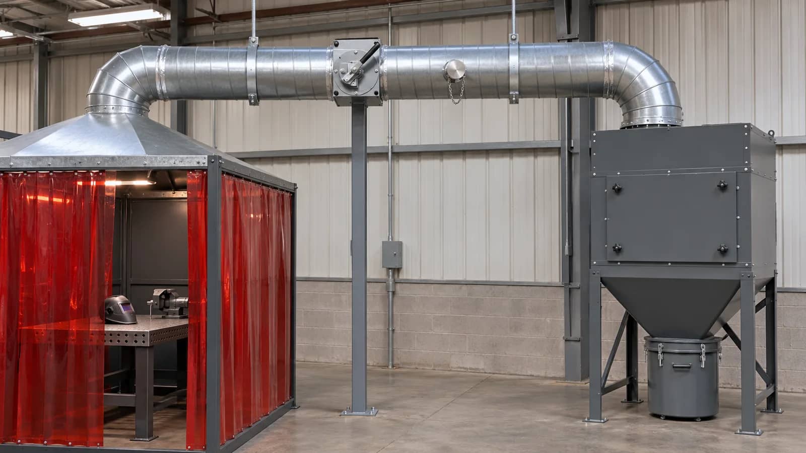
Choose capture geometry with the robot team
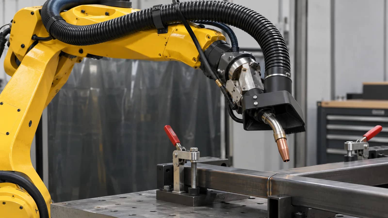
A torch pickup follows the weld source. Its shroud and hose can change the wrist envelope, routing and access for cleaning. A hood or partial enclosure can serve a larger work area. Check its openings, loading route and how the fixture or positioner changes the path of the plume. The cell integrator and ventilation designer should agree on the geometry together before either freezes drawings.
Review the limiting poses with the installed hose, fixture and guards. Include torch servicing and part exchange. Have the welding process owner check shielding and first-piece results with extraction running in its approved condition. Resolve interference or process changes before the layout is released.
Further reading: ABICOR BINZEL, torch-mounted source capture and hose routing ↗
Specify the collector, building and control boundaries
Ask for the intended flow and pressure at defined test points under stated branch and filter conditions. A catalog airflow number has meaning only with its test conditions. The installed duty point depends on fan behavior and the resistance of ducts, pickups, fittings and filters. Identify who designs and installs each segment, provides supports and access, and balances branches.
Assign make-up air, discharge routing, electrical supply and compressed air if required. Have the facility team address whether discharge or recirculation is appropriate for the contaminants and local requirements. Agree the control signals and decision logic for start, proven extraction, fault, low flow and restart. A motor-running indication alone does not establish airflow at the hood. Define who evaluates which faults affect the weld permit and what evidence proves the chosen response.
From source definition to site release
Record materials, weld states and personnel locations.
Check capture position, load access and hose sweep.
Agree duties for branches, utilities and signals.
Measure under agreed conditions and close exceptions.
Record baseline, fault response and service ownership.
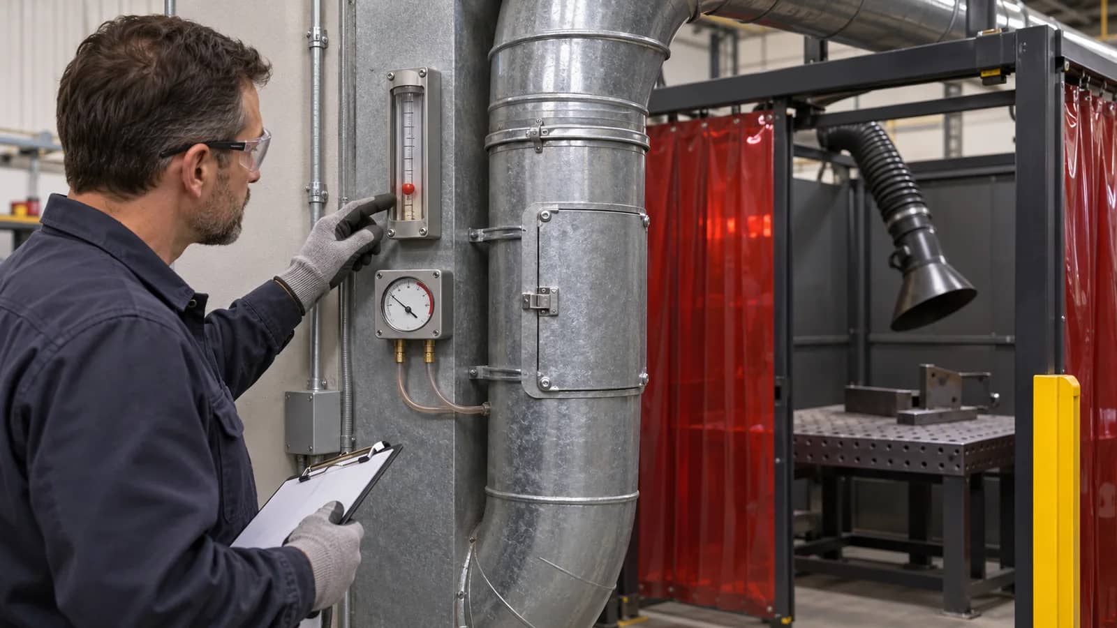
Agree commissioning and maintenance evidence
Request an as-built schematic with test points and branch states. The commissioning provider should record the operating conditions, methods, measured values and capture observations. Compare the measurements with the project criteria. Have the site's competent exposure assessor determine what separate occupational exposure evidence is needed. Capture observation and pressure readings answer different questions from sampling in a worker's breathing zone.
At handover, assign indicator checks, filter replacement, safe access and waste handling. Record the clean commissioning baseline, the planned response to changes and who retains the records. Revisit the design when a new coating, a changed seam position, extra stations or altered ductwork can change the source or the system resistance.
Further reading: HSE, local exhaust ventilation commissioning ↗
Cell-to-extraction interface responsibility matrix
Confirm the owners below with each supplier. Add operating conditions and agreed acceptance criteria to the interface drawing.
Copy the rows into your RFQ or investment worksheet.
| Interface | Confirm before quotation | Proposed owner | Evidence to request |
|---|---|---|---|
| Source | Material, coating, process, schedule. | Buyer process lead | Workpiece and source list. |
| Capture | Position, openings and operating states. | Ventilation designer | Capture layout and test conditions. |
| Robot envelope | Hose, torch, guard, fixture and positioner sweep. | Cell integrator | Witnessed critical poses and service access. |
| Process quality | Shielding and first-piece criteria with extraction running. | Welding and quality leads | Agreed weld and inspection record. |
| Ductwork | Flanges, branch states, supports and test ports. | Duct designer and installer | As-built schematic and balancing record. |
| Collector | Operating point and filter conditions. | Extraction supplier | Duty data and commissioned readings. |
| Facility | Make-up air, utilities and discharge route. | Facility engineering | Installed service and discharge drawings. |
| Controls | Proven flow, alarm, stop and restart response. | Controls integrator | Signal list and witnessed fault tests. |
| Commissioning | Methods, test points and active stations. | Commissioning provider | Report with readings and observations. |
| Exposure | Work patterns and applicable assessment. | Site occupational health team | Assessment and follow-up record. |
| Filter and waste | Access, replacement and waste route. | Maintenance and facility | Service procedure and named owner. |
| Change control | Changes to source, tooling, branches or duty. | Buyer project lead | Recheck scope and updated baseline. |
Questions before specifying the scope
Can I specify extraction from the collector airflow alone?
Include capture geometry, pressure losses and simultaneous branches. Agree the measurement locations and operating conditions.
What changes when a pickup moves onto the torch?
Check the added hardware, hose motion, torch cleaning and shielding with the proposed setup.
Does a running fan establish capture?
Check flow and capture at the relevant pickup during the agreed weld and station states.
What should site acceptance include?
Agree measurement points, operating states, capture checks, signal responses and the applicable exposure assessment separately.
When should the system be reviewed again?
Reassess affected conditions after changes to process, material, capture geometry or the duct network.
References and further reading
Define the extraction boundary in your RFQ
Share the cell layout, process, material and facility interfaces. TubeFrame can help coordinate equipment and integration scope for review with the responsible site specialists.
Discuss your welding cell ↗