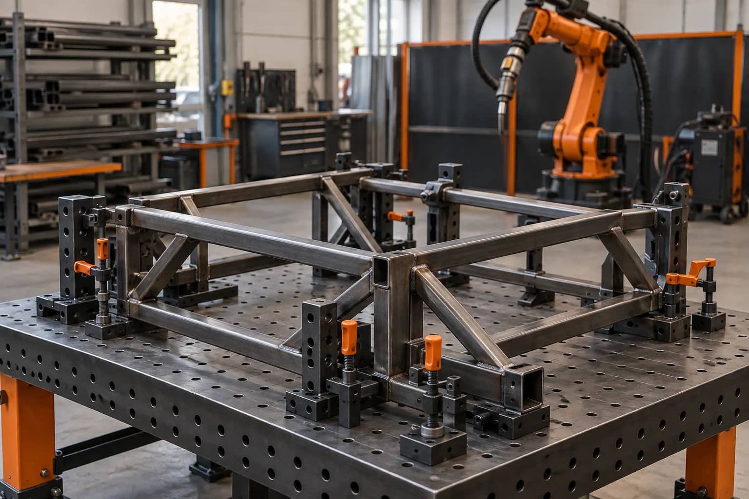
Fixture release decision: the minimum record
Record these three things before authorizing fixture manufacture or cell integration. The project drawing and trial protocol—not this guide—set the numeric limits.
- Controlled input
- Part-family and drawing revision, incoming fit-up range, functional datums and the approved weld sequence.
- Witnessed trial
- Named nominal and boundary parts, torch/cable clearance, load/unload sequence and after-cooling dimensional results.
- Accountable disposition
- Pass criteria, measurement record, deviations, re-test owner and sign-off authority for every variant.
Hold release when a specified part cannot be located, welded, removed and measured against its agreed criteria—or when a failed gate has no assigned corrective action and re-test.
Start with the frame family and the acceptance boundary
A fixture can repeat a bad input with impressive consistency. List every frame variant, tube profile, cut and bend condition, joint, drawing revision, weld requirement and expected production mix before specifying hardware. Select a representative nominal part and the worst credible fit-up condition allowed by the incoming specification. If the part cannot be located without forcing a tube into shape, solve the upstream variation or explicitly approve a correction strategy; do not hide it with stronger clamps.
The buyer should name the finished-frame dimensions that matter after unclamping and cooling, not only dimensions while the part is restrained. Record the measurement method, datum reference, sample count and inspection owner. Those values are project-specific; there is no responsible universal millimetre tolerance for every tube frame.
- Freeze drawing revision and part-family limits before tool release.
- Separate incoming-part acceptance from finished-weld acceptance.
- Agree which representative and boundary parts will be tried.
CAD-ready is not production-ready
A clean model says little about real tube straightness, cut length or joint gap.
Passing in the jig does not prove the cooled frame meets drawing after release.
A single part cannot prove variant changeover or boundary fit-up.
Locate from functional datums; clamp without blocking the weld
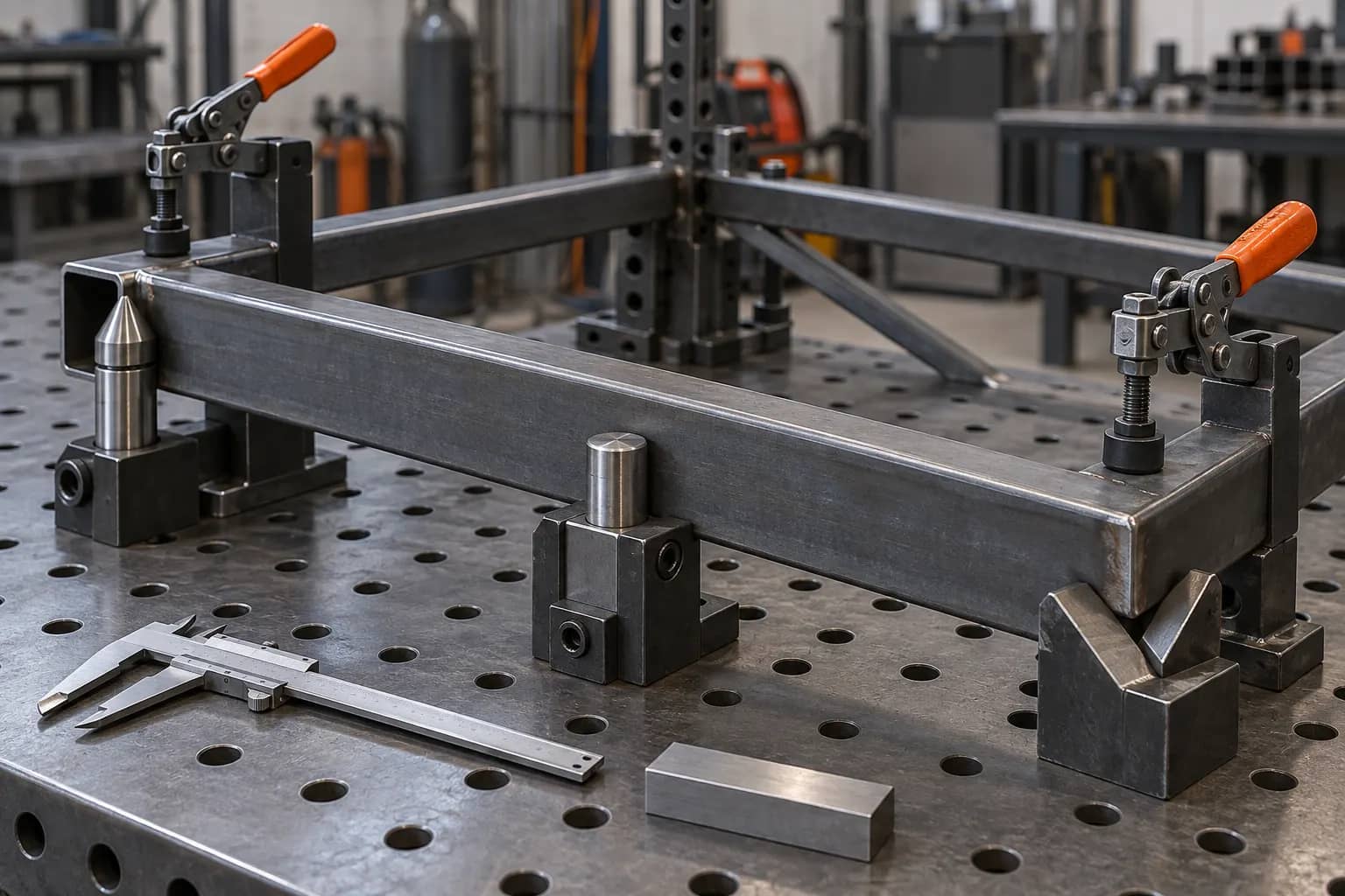
Choose locating surfaces that connect to the customer's functional assembly datums. A primary support establishes the first plane; secondary and tertiary references control the remaining degrees of freedom without overconstraining a variable tube. Use accessible, replaceable locating faces where wear or spatter is likely. Document the load order so two operators do not create different part positions with the same hardware.
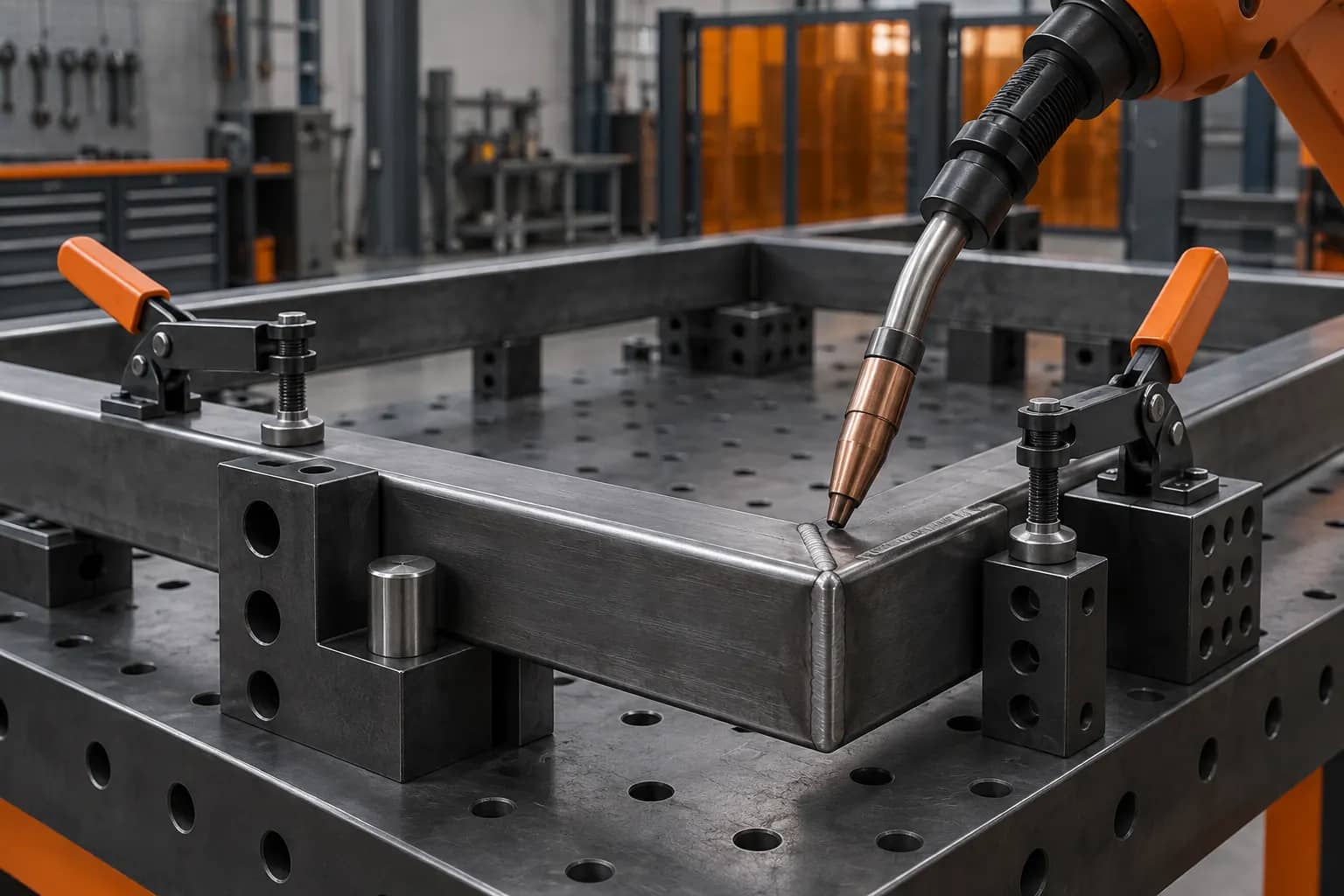
Clamps must hold the joint during tacking and welding but leave torch, nozzle, sensor, fume path, inspection and maintenance clearance. Test the full gun posture and cable sweep at both ends of each seam—not only the robot TCP in one pose. Miller and Yaskawa both stress part fit-up and access during automation feasibility. Their general advice becomes a release gate here: demonstrate the worst credible part in the proposed fixture.
- Datum map and locating-surface drawing
- Clamp, tack and unclamp sequence with operator reach
- Collision/clearance check for the actual torch package
Further reading: Miller Electric — automation readiness ↗ · Yaskawa — robot welding feasibility ↗
Prove distortion control after the clamps are released
Weld shrinkage can change a frame after unclamping. TWI's fabrication guidance explains how tack order, joint gap and balanced sequence affect distortion, while its restraint guidance warns that a rigid jig can retain stress and even contribute to cracking in susceptible work. Therefore, agree the tack and weld sequence with the welding engineer, measure the frame in the fixture, then measure it again after release and cooling.
Do not promise that a heavier fixture or more clamping automatically fixes bow or twist. If the trial fails, trace whether the cause is incoming geometry, datum choice, tack sequence, heat input, unsupported span or release order. Change one controlled variable, document it, and rerun representative parts before design freeze.
- Record sequence and weld-procedure revision used for the trial.
- Measure the named critical dimensions after release and cooling.
- Keep a deviation-and-retest log rather than accepting one attractive sample.
Further reading: TWI — distortion control by fabrication technique ↗ · TWI — restraint and welding fixtures ↗
Fixture release path
Drawing, variants, welds
Locate and load order
Torch, cable, operator
Tack, sequence, release
Measurements and owner
Make changeover and ownership part of the design
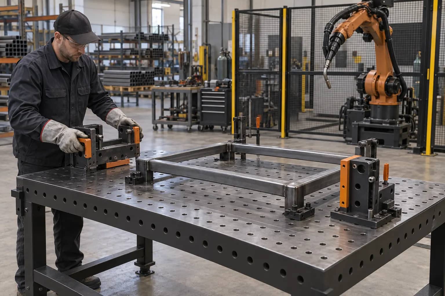
A family fixture needs positive, mistake-resistant settings for each approved frame—not a collection of unlabelled shims. Define what changes, who verifies the setting, where programs and fixture revisions are controlled, and how the first part after changeover is released. If a positioner is involved, check balanced loading, clamp access, index clearance and a safe removal path with the actual workpiece mass.
For procurement, ask who supplies datum blocks and wear parts, who validates the fixture against parts, who owns drawing changes, and whether trial rework and re-test are in scope. A quote that says only ‘welding fixture included’ leaves the most expensive interfaces undefined. Send the matrix below with representative drawings to obtain a project-specific fixture concept and test plan.
- Variant setting sheet and first-piece check
- Spare/wear-part list and revision owner
- Supplier–buyer split for samples, rework and validation
Tube-frame fixture release matrix
Copy these rows into the fixture RFQ. Enter project-specific limits, named owners and pass evidence before design release; the cells are prompts, not pre-approved tolerances.
Copy the rows into your RFQ or investment worksheet.
| Gate | Define with supplier | Stop / rework trigger | Evidence to retain |
|---|---|---|---|
| Part family | Variants, drawing revisions, material and tube profiles | Unlisted variant or undocumented revision | Controlled part list and representative samples |
| Incoming fit-up | Cut, bend, gap and straightness limits | Part must be forced into the fixture | Incoming measurement and boundary samples |
| Datum scheme | Functional primary/secondary/tertiary references | Ambiguous or competing locating faces | Datum map and repeat-load check |
| Clamp/tack order | Sequence and replaceable contact points | Operator-dependent position or blocked tack | Loading instruction and observed trial |
| Torch access | Weld list, gun posture and cable sweep | Nozzle, sensor or cable collision | Joint-by-joint access record |
| Thermal sequence | Approved tack/weld order and restraint | Crack risk or uncontrolled movement | Trial log tied to weld procedure |
| After-release shape | Critical dimensions after cooling | Passes clamped but fails free state | Inspection report and sampling method |
| Changeover | Positive settings and first-piece check | Uncontrolled shims or wrong program | Variant sheet and witnessed swap |
| Removal/service | Unclamp route, access and wear items | Trapped frame or unreachable repair | Observed removal and maintenance list |
| Responsibility | Sample, rework, re-test and revision owners | Open interface at shipment | Signed action log and release record |
Frequently asked questions
What should be fixed before a tube-frame fixture is designed?
Freeze the relevant drawing revisions, part-family boundaries, functional datums, incoming variation, weld list and finished-frame acceptance method. Otherwise the fixture may lock in the wrong geometry.
Can a clamp eliminate welding distortion?
No. Restraint can limit movement during welding but the assembly may move after release, and excessive restraint can increase residual stress. Validate the actual tack/weld sequence and inspect after cooling.
How do I know the robot can reach every joint?
Review each joint with the proposed torch, nozzle, cable and part orientation; test representative and boundary parts. A robot-reach number alone does not establish collision-free weld access.
What must be checked after a frame changeover?
Confirm the correct fixture settings and program revision, then inspect the first accepted part against the agreed datum and weld criteria before releasing the variant for production.
Original technical sources
Ask for a fixture concept against real parts
Send frame drawings, variant mix, weld and finished-dimension requirements, representative parts and target output. Request a datum/access concept and trial acceptance plan before approving tooling.
Discuss a tube-frame project ↗